This project was part of the 24-677 Special Topics: Linear Control Systems course at Carnegie Mellon University. The purpose of this assignment was to look at and design various ways of controlling an autonomous vehicle, in this case a Tesla Model 3, around a sometimes specified track. The various controllers analyzed and developed are the following:
- Proportional, Integral, and Derivative (PID) Controller
- Lateral Full-State Feedback Controller
- Lateral Optimal Controller
- Extended Kalman Filter (EKF) Simultaneous Localization And Mapping (SLAM) Controller
We used a bicycle model to describe the vehicle dynamics where the car is modeled as a two-wheeled vehicle with two degrees of freedom defined separately in longitudinal and lateral dynamics. The image below shows the two degrees of freedom where the v represents movement in the forward direction of the vehicle, while the 𝛿 represents change in the direction perpendicular to the vehicle via the angle of the front wheel.
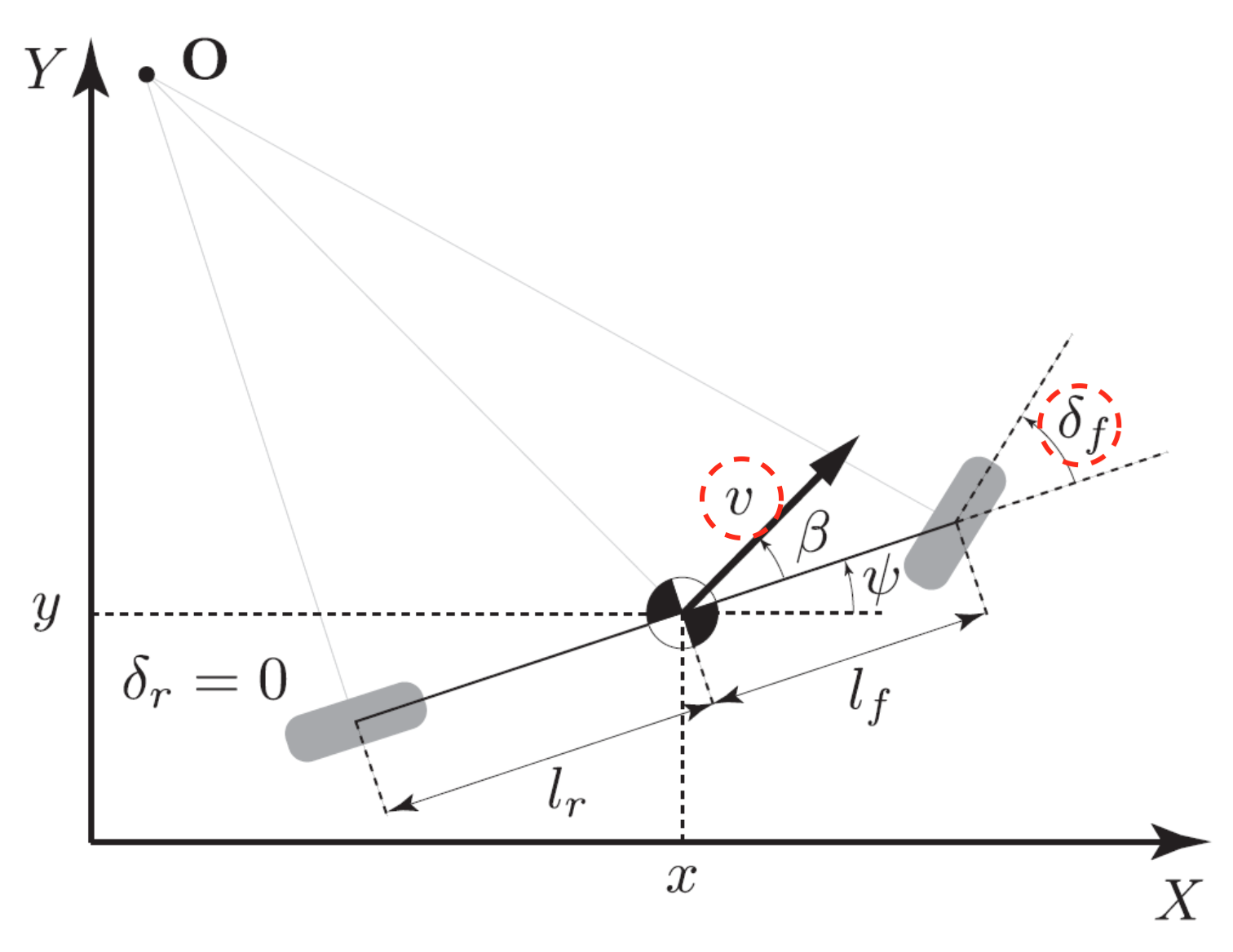
To simplify the controller we control the lateral and longitudinal states separately where, given inputs v and 𝛿, we define the states by the vehicle coordinates x, y and the vehicle’s body yaw angle ψ. This, along with their respective first-derivative, gives us a full model to describe the dynamics of the vehicle. In the equations below we can see the inputs u, the states s1 and s2, and the observable states y. The F in the inputs represents the force the driver exerts on the accelerator, correlating directly to the velocity.


The four controllers are built on a state space model describing the vehicle dynamics. The system dynamics in linear form for the lateral and longitudinal systems looks like the following:


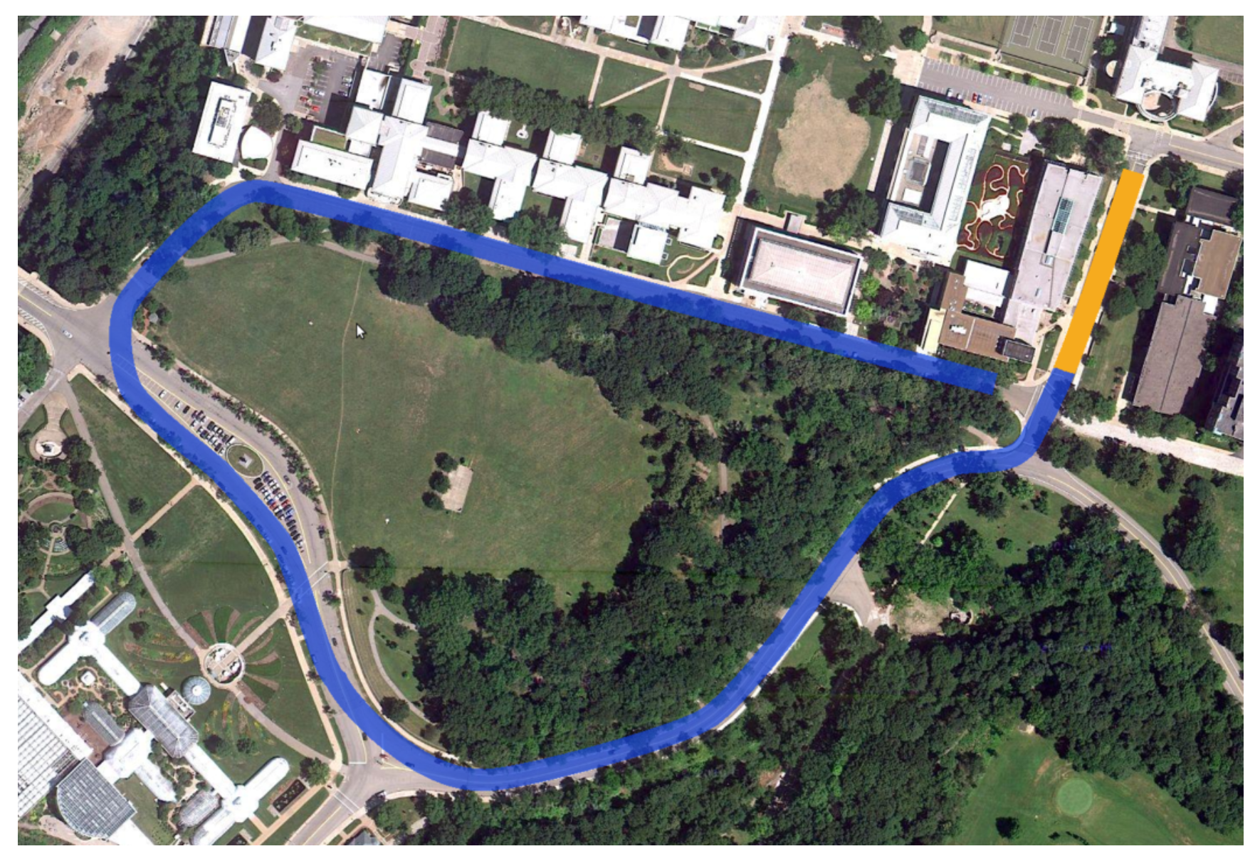
The trajectory of the vehicle is the famous buggy track encircling Flagstaff Hill in Schenley Park, Pittsburgh outlined in the image below.
The project was designed solely in Webots—an open-source robotics simulation software—and performance of each controller evaluated with figures and plots generated at the simulations’ conclusion. All four controllers were developed in Python.
PID Controller
The PID controller is broken up into two parts: a longitudinal controller and a lateral controller. The inputs to the system, i.e. the driver functions that control the car, are the steering angle 𝛿 and a throttle input derived from the desired longitudinal force F. The steering angle corresponds to the lateral controller while the force corresponds to the longitudinal. These are shown in the system dynamics described above.
A PID controller is an error-based controller that requires tuning proportional, integral and derivative gains. I designed a PID lateral controller and a PID longitudinal controller. The measured error is taken as the offset from the position of the vehicle and the center of the trajectory.
Performance of the controller is evaluated based on plots generated once the simulation is complete, showing a visualization of the car’s trajectory and variations of states with respect to time. Performance criteria:
-
- Max time to complete loop = 400 sec
- Max deviation from reference trajectory = 10 m
- Average deviation from reference trajectory = 5 m
The top-left plot shows the position of the vehicle along the track. The bottom-left plot shows the distance of the vehicle relative to the center of the trajectory; from this plot we can see a max deviation of 7 m. The remaining six plots show F, 𝛿, x_dot, y_dot, ψ, ψ_dot plotted with the time taken to complete the track. From all the plots with the exception of the trajectory on the top-left we can see the time taken to complete the track is roughly 150 sec. Therefore, from these results, it’s clear the ideal performance was met.
The video below shows a sped-up simulation of the car with the PID controller.

Lateral Full-State Feedback Controller
In this exercise I designed a state feedback controller using pole placement for the lateral controller and reused the PID longitudinal controller.
I first analyzed the controllability and observability of the system at various longitudinal velocities. At all the speeds chosen, the system is fully observable and controllable.
The feedback controller required implementing a gain matrix K such that u = –Kx where x represents the states and u is the control input. Pole placement in this part was done manually, where the K matrix correlated directly to the chosen poles. The poles of the transfer function are the eigenvalues of the system matrix. From the equation u = –Kx, it’s clear that the chosen poles in the K matrix affect the control inputs that guide the vehicle through its trajectory.
Performance criteria:
-
- Max time to complete loop = 350 sec
- Max deviation from reference trajectory = 9 m
- Average deviation from reference trajectory = 4.5 m
The plots on the right again show successful completion of the course with a max deviation of 8.4 m and a completion time of 150 sec. The video shows a sped-up simulation of the feedback controller.

Lateral Optimal Controller
I designed an optimal controller for the lateral component and, similar to the feedback controller, reused the PID longitudinal controller. The optimal controller is a discrete-time infinite horizon Linear Quadratic Regulator (LQR) controller.
Implementing the LQR controller required generating Q and R matrices, which correspond to the state and control weights respectively. The LQR controller aims to regulate the linear system in following a trajectory over time, minimizing the cost function of the system. The cost function is quadratic in taking the sum over the states and the inputs at every time-step, and multiplying these by the Q and R matrices.
Performance criteria:
-
- Max time to complete loop = 250 sec
- Max deviation from reference trajectory = 7 m
- Average deviation from reference trajectory = 3.5 m
The video shows a sped-up simulation of the LQR controller and the image shows the performance.

EKF SLAM
I reused the LQR controller for the lateral component and PID controller for the longitudinal. This effort constituted in designing and implementing an Extended Kalman Filter (EKF) with Simultaneous Localization and Mapping (SLAM) to estimate the position and heading of the vehicle, both of which were previously assumed to always be available.
Since in some real world scenarios we may not have accurate localization information from the GPS—erroneous data due to driving through a tunnel or tall infrastructures—we use data we do know to estimate these variables. In this case, we use the change in position, in both x and y, and heading of the vehicle frame along with range and bearing measurements of map features to calculate the position x, y and heading ψ of the vehicle.
I took 8 different map features’ m_x and m_y positions, which were static, to define and update the state vector. The state vector also includes the x, y and ψ of the vehicle. I was able to estimate the position of the map features using the range and bearing measurements of the vehicle relative to those features. The range measurement is the distance to each feature from the vehicle and the bearing measurement is the angle between the vehicle’s heading and the ray from the vehicle to the feature. The state vector and the measurement system are defined as such:

Using this system I predicted the state and error covariance, then used these to correct the Kalman gain and update the state and the error covariance, repeating the process every time-step. This is also known as the “Hi-Five” Kalman Filter Algorithm.
Performance criteria:
-
- Max time to complete loop = 250 sec
- Max deviation from reference trajectory = 10 m
- Average deviation from reference trajectory = 5 m
Similar to the three controllers above, the video shows a sped-up simulation of the EKF and SLAM implementation and the image shows the performance.